

 The purpose of this design guide is to acquaint the irrigation designer with some of the unique considerations involved in designing linear irrigation system installations. This guide does not attempt to cover the basic linear irrigation system design considerations such as water quality, crop consumptive use requirements, water management, climate, etc; it is assumed the irrigation designer will have already investigated these factors, and is now faced with having to consider how a linear irrigation system might be applied to a specific situation. There are many variables to be considered, and specific recommendations are sometimes difficult to determine, but the well-informed system designer should be able to combine the information in this design guide with his own knowledge and information from other sources to arrive at a well-designed irrigation tool for the farmer.
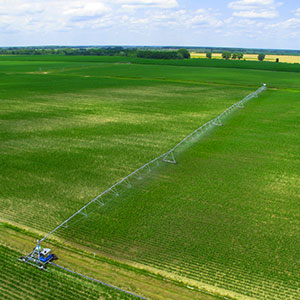
The initial field/system design for the linear System begins with the determination of field dimensions and the location of a ditch, either at the edge of a field or through the approximate center of the field. This, of course, determines whether we have and end feed or center feed system. Also there are two possibilities concerning the ditch: it may be an existing ditch or we may have to locate and construct a new ditch.
Definition of dimensional terms
End feed and existing ditch (left picture)
Measure field at “A” and “B”. The shortest dimension, less 12 feet for inlet length, for dirt ditch, and 7 feet for concrete ditch, less 6 feet for end tower or overhang clearance is the longest linear irrigation system we can install (assuming that span lengths can be arranged to fit).
End feed and new ditch (right picture)
Measure field at “C” and “D”. The shortest dimension, less 6 feet clearance, less 12 feet inlet, less 4 feet ditch (centerline) is the longest system that we can install (considering span lengths).

Center feed and existing ditch (left picture)
Measure field at “E”, “F”, “G” and “H”. The shortest dimension “E” or “G” added to the shortest of “F” or “H” will be used to determine our irrigation system design length. Remember to add 1.7 feet for the transition pipe. Also deduct 6 feet from each end for clearance. Also remember that the free-standing span (with boss unit) in the center of the field must be positioned approximately 12 feet away from the center line of the ditch, using the span flange as the calculation point.
Center feed and new ditch (right picture)
Measure field at “J” and “K”. The shortest dimension, if any difference will be used to determine the maximum system length, less 6 feet on each side for clearance. At the approximate center of the system, locate the free-standing span, considering GPM requirements, pipe sizing, available span lengths, etc. Remember to add 1.7 feet for transition pipe. Once the free-standing span is located, calculate the position of the centerline of the ditch approximately 12 feet outside of the flenge on the linear cart.

End of run adjustments
 Consider potential for moving system beyond field boundary for convenience during cultivation and harvest operation.

As an installer of Pivot systems, I found this article on the design of mechanized irrigation systems with canal pumping on a rectangular plot very useful.