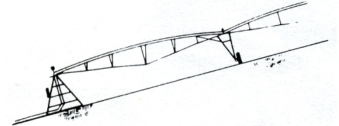
There’s to measure all questionable field slopes to assure Pivot irrigation system compatibility.
Slope percentage equals rise divided by run.
% Slope = rise / run
Slope limitations
Structural and drive unit power design limit the climbing capability of center Pivots to the following slopes.
Slope limits (%) – Standard and low profile systems
Tire size 0″ – 6″ ridges
| Span Length | 11.2 X 24 | 14.9 X 24 | 16.9 X 24 |
| 105′ – 10″ | NA | 8 | 8 |
| 105′ – 6 5/8″ | 24 | 21 | 19 |
| 105′ – 8″ | 8 | 18 | 17 |
| 126′ – 8″ | NA | 12 | 12 |
| 126′ – 6 5/8″ | 8 | 18 | 17 |
| 147′ – 6 5/8″ | 5 | 14 | 14 |
| 160′ – 6 5/8″ | NA | 12 | 12 |
| 183′ – 6 5/8″ | NA | 10 | 10 |
| 170′ – 6″ | 5 | 14 | 14 |
| 185′ – 6″ | NA | 12 | 12 |
Tire size 6″ – 12″ ridges
| Span Length | 11.2 X 24 | 14.9 X 24 | 16.9 X 24 |
| 105′ – 10″ | NA | 4 | 4 |
| 105′ – 6 5/8″ | 18 | 14 | 13 |
| 105′ – 8″ | 8 | 14 | 12 |
| 126′ – 8″ | NA | 8 | 8 |
| 126′ – 6 5/8″ | 8 | 14 | 12 |
| 147′ – 6 5/8″ | 5 | 10 | 10 |
| 160′ – 6 5/8″ | NA | 8 | 8 |
| 183′ – 6 5/8″ | NA | 5 | 5 |
| 170′ – 6″ | 5 | 10 | 10 |
| 185′ – 6″ | NA | 8 | 8 |
High profiles limited to 6 5/8″ and 6″ spans. Maximum climbing slope is 5% and ridges of 6″ or less.
Ground clearance (feet) – Standard and high profile
Crop clearance must be considered; often a drive unit will handle the slope, but provide inadequate crop clearance. The table below is for a hill midway between drive units.

Percent slope = slope a + slope b / 2
Standard profile
| Span Length | 0% | 5% |
| 105′ – 10″ | 9.5′ | 6.9′ |
| 105′ – 8″ | 10.2′ | 7.6′ |
| 126′ – 8″ | 9.9′ | 6.8′ |
| 126′ – 6 5/8″ | 10.2′ | 7.1′ |
| 147′ – 6 5/8″ | 10.0′ | 6.3′ |
| 160′ – 6 5/8″ | 9.2′ | 5.2′ |
| 183′ – 6 5/8″ | 9.0′ | 4.4′ |
| 170′ – 6″ | 8.9′ | 4.7′ |
| 185′ – 6″ | 8.8′ | 4.2′ |
| Span Length | 10% | 15% |
| 105′ – 10″ | 4.3′ | 1.6′ |
| 105′ – 8″ | 5.0′ | 2.3′ |
| 126′ – 8″ | 3.6′ | 0.5′ |
| 126′ – 6 5/8″ | 3.9′ | 0.8′ |
| 147′ – 6 5/8″ | 2.7′ | – |
| 160′ – 6 5/8″ | 1.2′ | – |
| 183′ – 6 5/8″ | – | – |
| 170′ – 6″ | 0.40′ | – |
| 185′ – 6″ | – | – |
High profile
| Span Length | 0% | 5% |
| 126′ – 6 5/8″ | 13.5′ | 10.4′ |
| 147′ – 6 5/8″ | 13.25′ | 9.6′ |
| 160′ – 6 5/8″ | 12.4′ | 8.4′ |
| 105′ – 6 5/8″ | 13.7′ | 11.2′ |
Maximum slope absorption permissible
Slope absorption at the drive unit must be considered. The ball and socket joint on undertruss spans allows a sum of slope (a + b) or (b + c) without significant torsional loading.

| Maximum slope absorption of Tower flex | |
| Span length | Slope (a + b) % or Slope (b + c) % |
| 105′ – 6 5/8″ | 30 % |
| 105′ – 10″ | 14 % |
| 126′ – 6 5/8″ | 30 % |
| 126′ – 8″ | 24 % |
| 147′ – 6 5/8″ | 30 % |
| 160′ – 6 5/8″ | 30 % |
| 170′ – 6″ | 30 % |
| 185′ – 6″ | 30 % |
Slope absorption at the drive unit also occurs as a torsional load on the span when adjacent drive units encounter opposite slopes. These slopes are measured along the actual drive unit paths.
Pivot flex requirements
Is a Pivot flex required? Assuming the Pivot pad is level, a Pivot flex is required when the slope from pad to first drive unit exceeds 4% (either up or down).

| Span length | Distance up or down |
| 105′ | 4.1′ |
| 126” | 5.0′ |
| 147′ | 5.8′ |
| 160′ | 6.4′ |
| 170′ | 6.8′ |
| 185′ | 7.4′ |
On an uniform continuous slope in the area around the Pivot, installation of the Pivot pad parallel (in same plane) to the field slope would eliminate need for the Pivot flex.

General slope guidelines for heavy soils
Runoff may be a factor on heavy soils. Consider soil type, infiltration rate, crop, tillage practices, and application rates. The system may tolerate the slope, but will the water stay there?
| Slope | Application rate reduction |
| 0-4% | 0% |
| 5-8% | 20% |
| 9-12% | 40% |


Leave a Reply